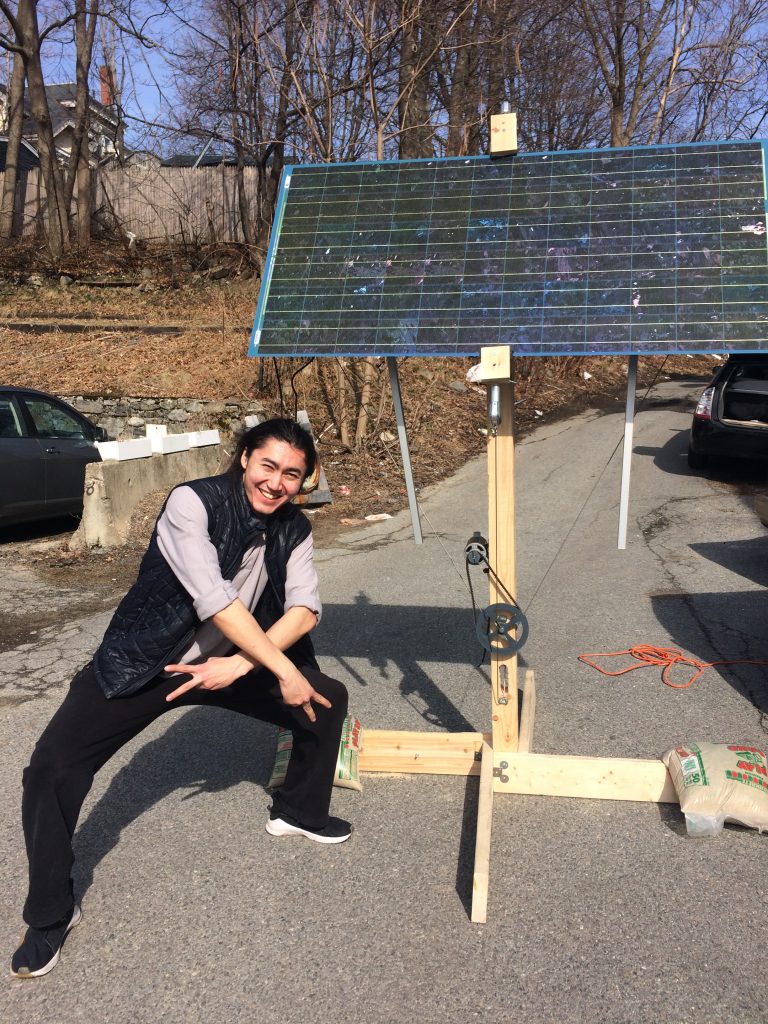
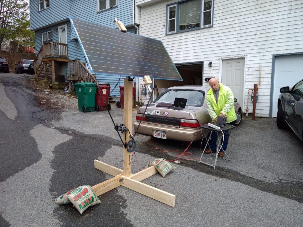
I had an idea for a solar tracker system that has two axes controlled by a single motor. It looked great on paper but a major flop in reality. I made pretty significant mechanical simplifications in my design which accumulated into an unstable (yet somewhat working) structure.
I designed and manufactured the mechanical system myself, and with Jean’s help I assembled it. I salvaged an electric motor from an old treadmill that I got on eBay to use as an actuator. I designed and assembled a custom motor drive controlled by an arduino that senses the location of the sun using a simple quadrant detector (that I 3D printed at a local MakerSpace).
I was curious in this project because I wanted to gain some mechanical engineering experience. Even though the design didn’t work, I am happy with the manufacturing and development experience that I got from working on it. I also gained a better insight into mechanical behaviors described by second-order differential equations (damping, mechanical resonance, spring action, etc.). This is extremely valuable because it puts the abstract mathematical equations into a more natural physical representation that is easier to process on the fly.
Big thanks to Jean P Amazan for his help in assembling and mechanical troubleshooting!
This is how an H-bridge shoot through looks like! (Below) This happens if both high-side and low-side FETs of an H-bridge are on at the same time (which I could’ve sworn I accounted for with enough dead-time in my code).
I later implemented an H-bridge using relays because I didn’t really need to control the speed of rotation – just the direction. Here is how the motor changed its direction depending on the position of a homemade solar quadrant detector:


